Outer Wall / Inner Wall Split
The Problem With "Walls"
Snapmaker Orca already knows the difference between an outer wall and an inner wall - open the line type view in preview and they are drawn as separate feature types, in separate colors, tracked as distinct all the way through the slicer. What it will not let you do is act on it: both are assigned to a single extruder, controlled by one setting called Walls. The slicer knows the outer loop is doing a different job from the loops behind it, and then sends them both to the same nozzle anyway. On a single-nozzle printer that is unavoidable. On the Snapmaker U1, with four independent heads, it is a missed opportunity - because every perimeter loop plays a different role. The outermost loop, the one you can see and touch, determines surface finish, dimensional accuracy, and detail resolution. Every loop behind it is structural: it reinforces the shell, transfers load to the infill, and adds wall thickness. These are different jobs, and they do not need the same nozzle.
What FOrcaSlicer Does Differently
FOrcaSlicer splits Walls into two independently assignable features:
| Feature | Role | Recommended nozzle |
|---|---|---|
| Outer Wall (OW) | Visible surface, detail, dimensional accuracy | Small (0.2 mm) |
| Inner Wall (IW) | Structural reinforcement, shell thickness | Larger (0.4 mm+) |
Each can be assigned to any of the four U1 heads independently, with its own nozzle diameter, filament, line width, and speed. The distinction the slicer was already making becomes a distinction you can print with - and, crucially, it is not only a nozzle you get to choose per feature. It is a material.
As of 8.5, each feature is also printed at the line width and speed of the nozzle that actually prints it - set them in the per-nozzle tabs on the Quality and Speed pages - so the wider inner-wall nozzle runs at its own width and speed rather than inheriting the outer wall nozzle's.
The Gear Example
Gears are the clearest case for the split. The tooth flank is a precision surface - involute accuracy and finish determine whether a gear meshes smoothly or binds - and everything behind the flank is structure. A single gear is a weak test, though: real work means a set of them, and slicing a full plate is exactly where print time actually means something. The test print below is three copies of the same seven-gear set.
Download: 1M_gear_group.STL
All seven gears are module 1, 20 degree pressure angle, 6 mm face width. The helical gears use a 20 degree helix angle. They differ only in tooth count:
| Type | Tooth counts |
|---|---|
| Spur | 10T, 16T, 32T |
| Internal spur | 48T |
| Helical | 16T, 20T, 32T |
Two materials, one gear
This is where the split stops being a speed argument and becomes an engineering one.
A gear wants two different things from its material. The tooth flank wants lubricity - it is a sliding contact surface, and a slippery material runs cooler, quieter, and longer. Pure nylon (PA) is excellent at this. Everything behind the flank wants stiffness - a tooth that deflects under load loses its involute profile no matter how accurately it was printed. Carbon-fiber-filled nylon (PA-CF) is far more rigid, and far worse as a bearing surface.
You can only pick one for wall in stock. FOrcaSlicer lets you have both: PA on the outer wall, PA-CF on everything behind it. The tooth is slippery where it touches another tooth, and stiff everywhere else.
Note on the test print: the prints below use PETG on the wall and PETG-CF on everything else, standing in for PA and PA-CF. This is a preset limitation, not a printer one - Snapmaker's U1 presets only ship PA-family materials for the 0.4 mm nozzle, even though the other nozzles can print them perfectly well. The structural point is identical.
Sliced four ways
Two stock, two FOrcaSlicer:
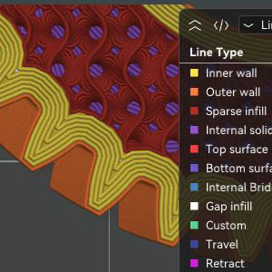
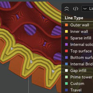
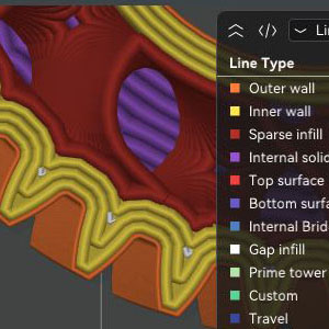
| Every loop 0.2 mm (stock) | OW 0.2 mm, everything else 0.4 mm | OW 0.2 mm, IW 0.4 mm, everything else 0.6 mm | Every loop 0.4 mm (stock) |
|---|---|---|---|
 |
 |
 |
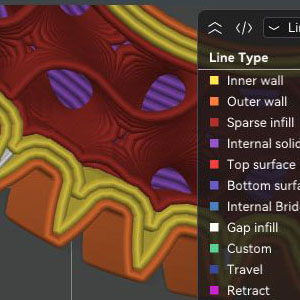 |
| Fine detail, slow print - 8h 39m | Fine detail, faster print - 5h 15m | Fine detail, faster print - 5h 5m | Less detail, fastest print - 4h 29m |
The two middle columns are the point. The tooth profile is identical to the all-0.2 print - the outer wall is still laid down by the 0.2 mm nozzle, so the flanks are unchanged. But the print finishes in roughly five hours instead of eight and a half, because everything behind the flank is being laid down by a nozzle two or three times wider. And the two middle columns are faster even with a wipe tower enabled - the tool changes a mixed-nozzle print requires do not eat the saving.
The all-0.4 column is the honest comparison for that time saving: yes, it is faster still - and it is the column where the teeth visibly lose definition. A 0.2 mm nozzle is still better at rendering the tooth tip fillet and the relief, simply because of the resolution it can put down. FOrcaSlicer gets you most of the speed of the slightly coarse print with none of the surface cost.
And there is a second win the clock does not show. Because the carbon-filled material is available to the inner wall in the FOrcaSlicer prints, the teeth in those two columns should end up more rigid than the stock prints - which are pure PA all the way through, flank and core alike. The FOS gears are not merely faster versions of the same part. They are a better part.
Time and Print Planning
The line type view shows what is actually happening - which nozzle lays down which feature, and how the loop count behind the outer wall collapses as the inner nozzle gets wider.
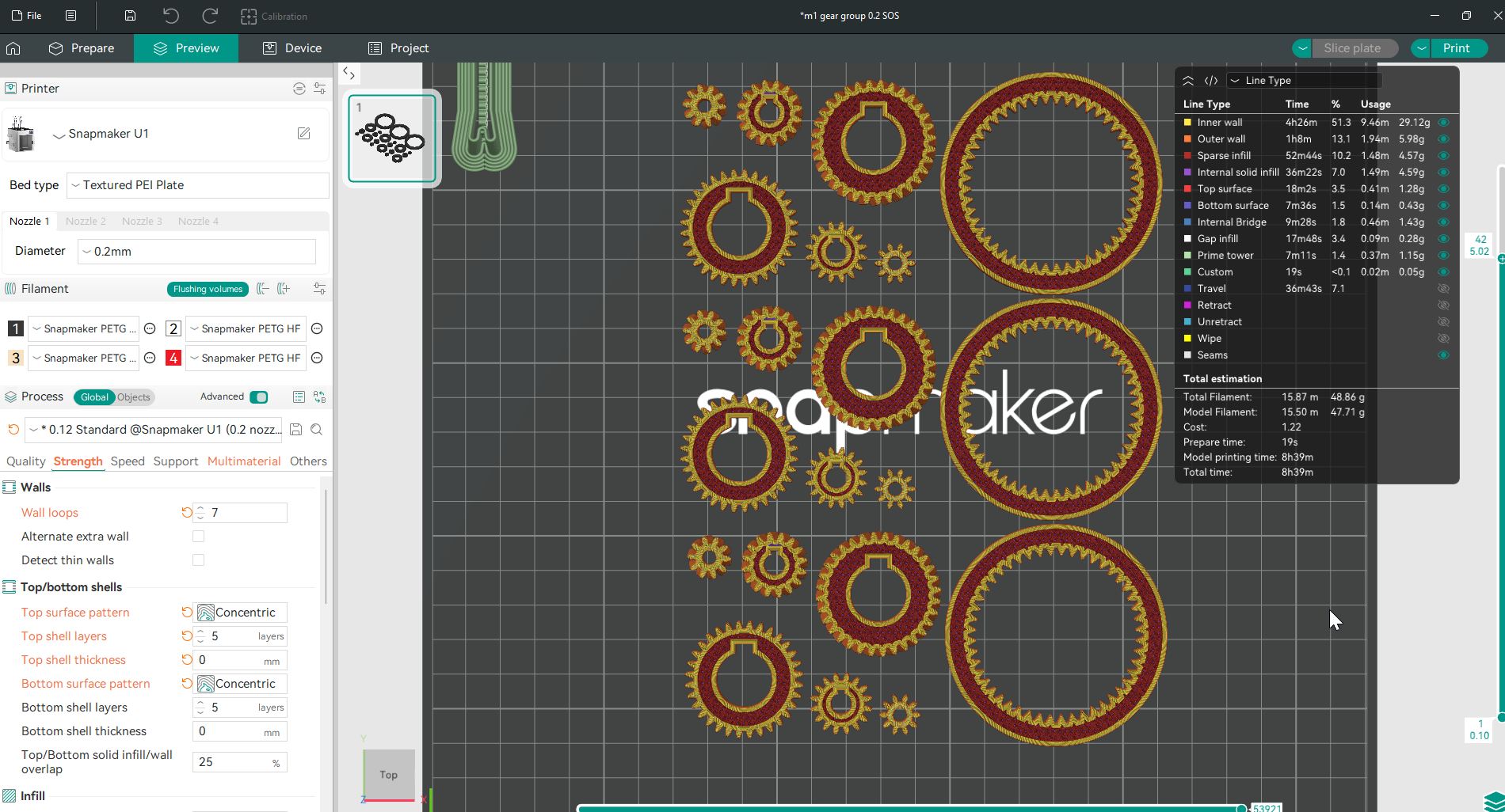 All 0.2 mm.
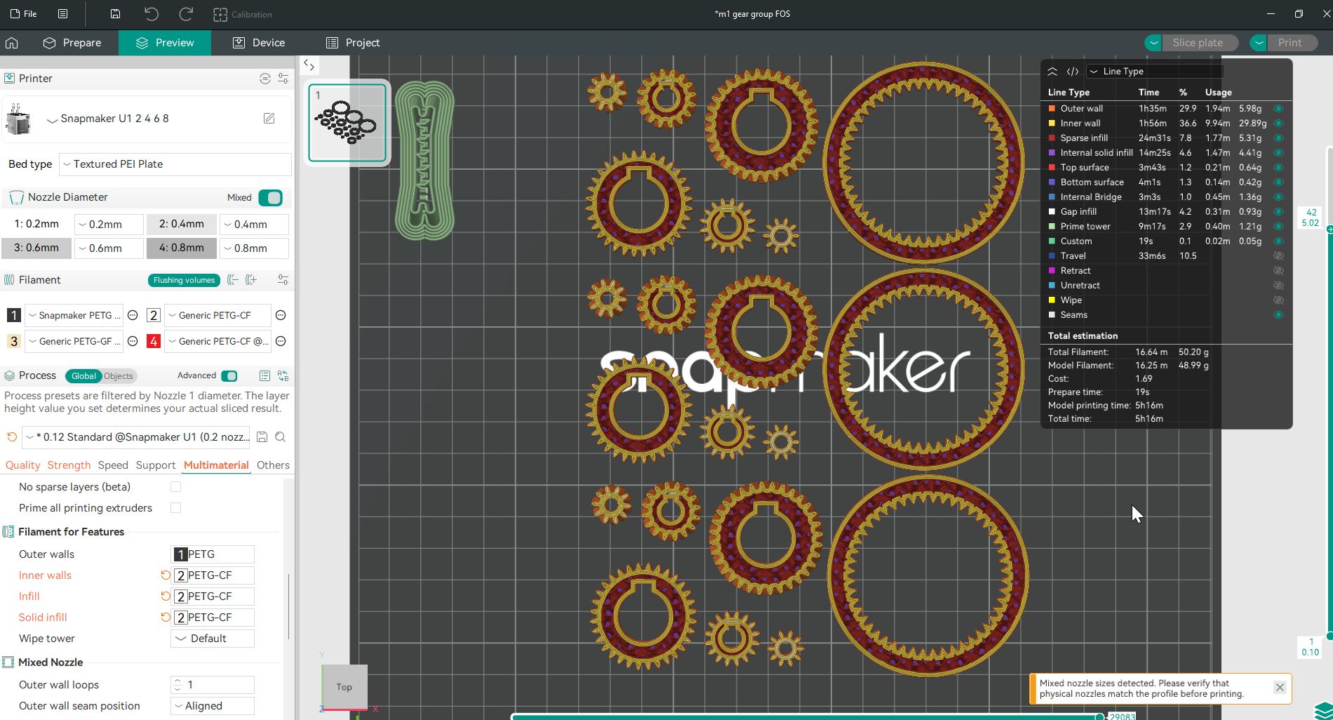 OW 0.2 mm, everything else 0.4 mm.
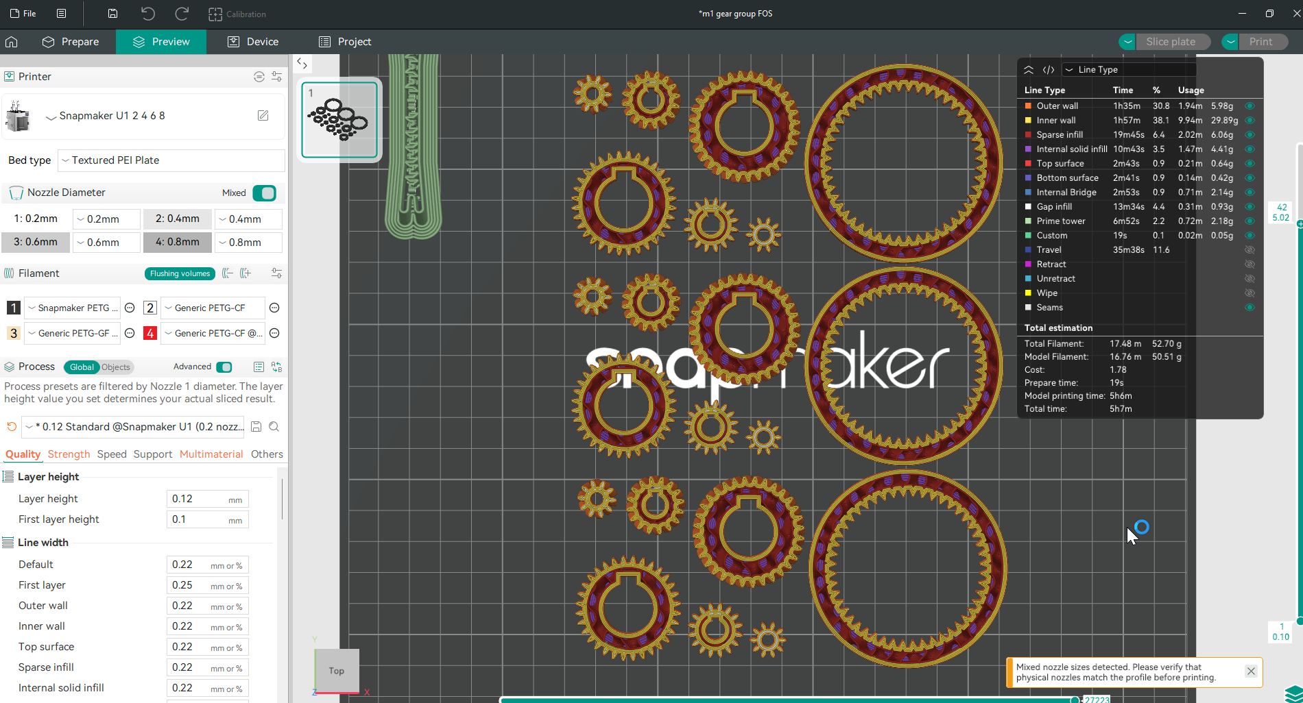 OW 0.2 mm, IW 0.4 mm, everything else 0.6 mm.
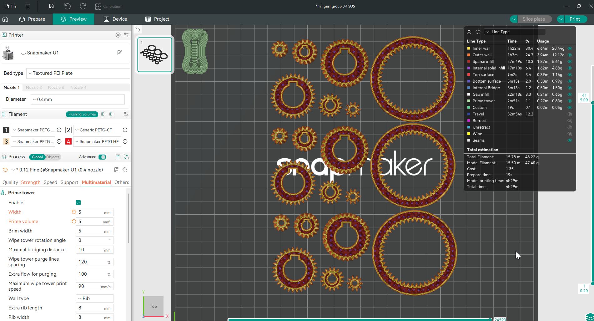 All 0.4 mm.
Filament Usage
The filament window breaks usage down per category and per filament, with subtotals and totals - which is where you can see exactly how much of the expensive, precise material you are actually spending on the surface, and how much of the cheap structural material is doing the rest.
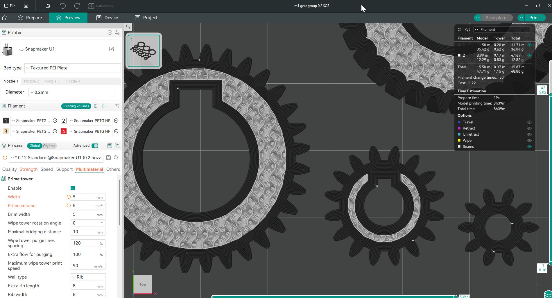 All 0.2 mm.
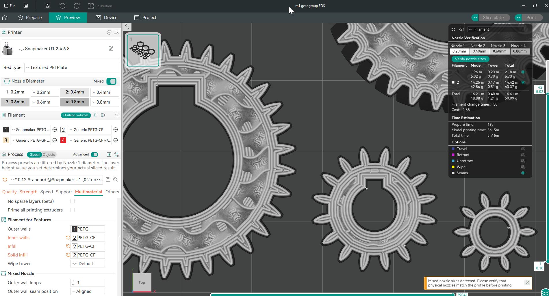 OW 0.2 mm, everything else 0.4 mm.
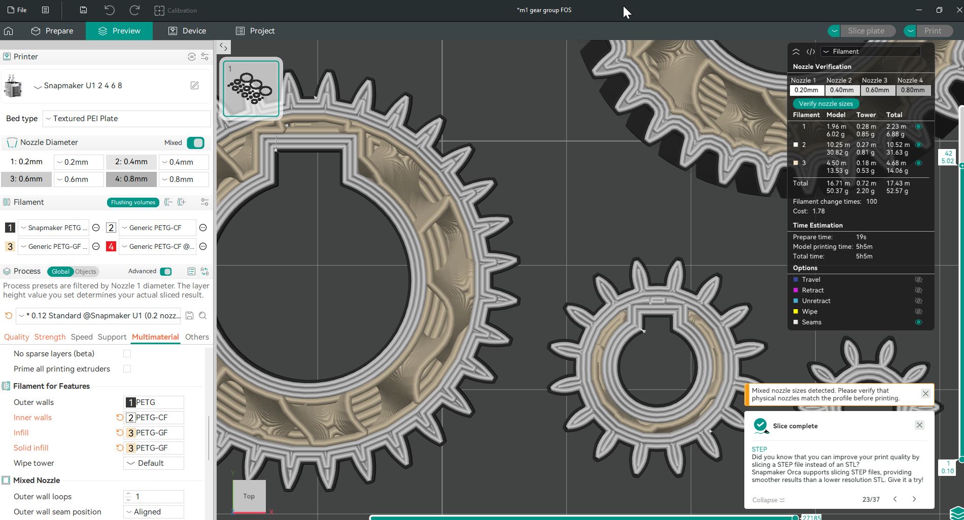 OW 0.2 mm, IW 0.4 mm, everything else 0.6 mm.
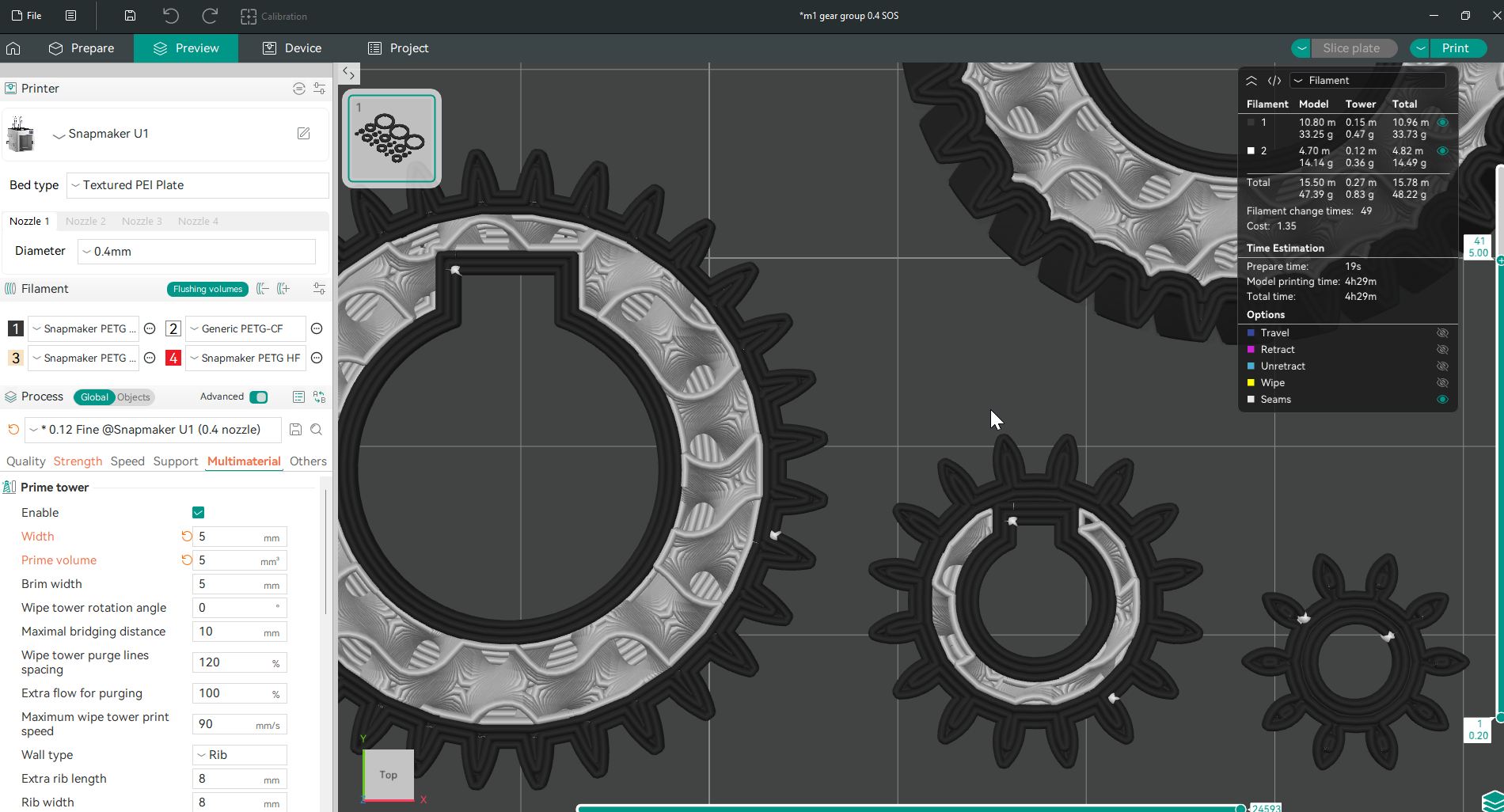 All 0.4 mm.
Settings
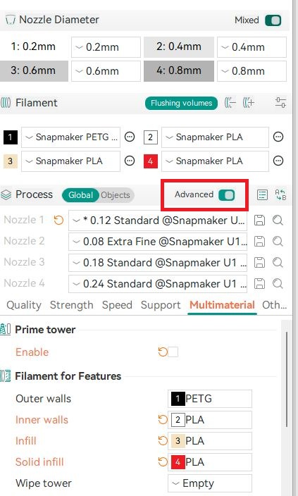
To configure the split, turn on Advanced mode in Process settings, then go to Multimaterial -> Filament for Features.
| Setting | Description |
|---|---|
| Outer walls | Which nozzle prints the outer wall loops |
| Inner walls | Which nozzle prints every loop behind the outer wall |
| Outer wall loops | How many loops count as "outer wall" (default: 1) |
Outer wall loops lets you designate more than one loop as outer wall - useful when you want two precision loops before handing off to the larger inner wall nozzle. If you set it higher than the total wall loop count, the field turns red: you have asked for more outer wall loops than there are walls.
The Gap Between OW and IW
When the outer wall and inner wall use different nozzle diameters, the spacing at the boundary between them is not the same as the spacing between two loops from the same nozzle. It cannot be - the two extrusions are different widths.
FOrcaSlicer handles this explicitly:
- Outer wall loops are spaced using the external perimeter spacing, derived from the outer wall nozzle.
- Inner wall loops are spaced using the internal perimeter spacing, derived from the inner wall nozzle.
- The boundary between them - the gap between the last outer wall loop and the first inner wall loop - is the average of the two: half the outer wall spacing plus half the inner wall spacing.
That is the same physical rule any two adjacent extrusions follow: each contributes half its own width. It is only worth stating because the two halves are now different sizes. The correction is applied automatically whenever the outer wall and inner wall are assigned to different nozzles - you do not configure it.
Line Widths Must Be Absolute
One thing to know if you build a custom process preset: specify line widths in millimeters, not as a percentage of nozzle diameter.
A percentage line width resolves against a single nozzle diameter, and in a mixed-nozzle print there is no single diameter for it to resolve against - the perimeter generator runs in the outer wall nozzle's context, so a percentage would silently apply the outer wall nozzle's diameter to extrusions being made by a completely different nozzle. The shipped U1 process presets already use absolute millimeters. A percentage will not throw an error; it will just quietly produce wrong flow on every nozzle but one.
Where This Goes Next
Splitting walls by nozzle is the foundation, and each feature now prints at its own nozzle's line width and speed. The next step is splitting them by layer height - letting the 0.4 mm inner wall nozzle lay thicker layers than the 0.2 mm outer wall nozzle, inside the same object. Today both still print on one shared layer grid, bounded by the finer nozzle in use.
See Known Limitations for what the shared layer grid currently costs you.