Technical Guardrails
FOrcaSlicer deliberately blocks, disables, or auto-corrects a handful of things. None of them are arbitrary. This page explains each one, so that when the software tells you no, you know why.
The Setup Wizard Is Skipped
What you see: FOrcaSlicer starts straight into the workspace. No first-run wizard.
Why: The Snapmaker wizard requires a Snapmaker account login and, once logged in, downloads the current Snapmaker preset set from Snapmaker's server. Those presets are built for a newer Snapmaker Orca release than the codebase FOrcaSlicer forked from. They have not been tested against the current FOrcaSlicer release, and may cause compatibility issues.
FOrcaSlicer ships with the Snapmaker OrcaSlicer 2.3.1 presets for the U1 built in. There is nothing the wizard needs to fetch.
System Preset Sync Is Disabled by Default
What you see: Automatic preset sync is off in Preferences.
Why: Same reason. Left on, sync may quietly pull down incompatible or untested presets in the background - with the result that a working install breaks a day later for no visible reason. Keeping those presets working is beyond the scope of the FOrcaSlicer release. This was a real failure mode on fresh installs before it was disabled.
Should you turn it on? No. If you need a preset FOrcaSlicer does not have, build it as a custom preset instead.
Foreign Presets (Bambu, Generic, Other Machines)
What you see: FOrcaSlicer will open a project or preset from another printer without crashing. It may not slice it usefully.
Why: A preset from a non-U1 machine has no values for any of the settings FOrcaSlicer added - outer wall loops, inner wall filament, color patch settings, per-nozzle diameters. Earlier versions read those missing values and crashed outright, on the Multimaterial tab, when adding a printer, and elsewhere.
Those crashes are fixed: missing FOS settings now fall back to safe defaults rather than dereferencing nothing. But a Bambu preset opened in FOrcaSlicer is still a Bambu preset. Treat it as a starting point to read, not a profile to print from.
The Outer Wall Nozzle Cannot Use Color Patch
What you see: Select the nozzle that is assigned as Outer Wall in the paint gizmo, and the Color Patch button is grayed out with a tooltip. The extruder stays in Original mode.
Why: Color Patch means "this color occupies the outermost N loops of the surface." The Outer Wall nozzle already occupies the outermost loops of the entire model - that is its definition. Color Patch on the OW nozzle would be asking the slicer to do what it is already doing.
The guard compares the selected painting extruder against the extruder assigned to wall_filament. If they match, Color Patch is unavailable for that extruder.
What to do instead: assign the color you want as a patch to a different nozzle - one not carrying the outer wall - and paint with that. See Color Patch.
Process Presets Are Selected per Nozzle
What you see: Each nozzle carries its own process preset (PRP). Rather than a single dropdown filtered by Nozzle 1's diameter, the Quality and Speed pages give each nozzle its own tab, and every feature is sliced with the line width and speed of the nozzle that prints it.
An object's filament is its outer wall: an object always carries a concrete filament - its outer wall - and its features otherwise follow the global Filament for Features assignment. There is no separate object "default"/"Global" fallback, so nothing silently pulls an unused nozzle into the print. To put a whole object on one filament, right-click it in the Objects list and choose Unify Object Filaments (or set it from the object settings window). The steps are in First Launch.
Why: Line width and speed are now resolved per nozzle (as of 8.5). Layer height and initial layer height are the exception - they stay a single global value bounded by the smallest nozzle in use, covered in the section below and in Known Limitations.
Mixed Mode: The Sync Confirmation Dialogs
The nozzle panel has a Mixed mode toggle, and it changes what happens when you edit a nozzle diameter.
| Mixed mode | Change a nozzle diameter | Result |
|---|---|---|
| Off (synced) | Confirmation dialog appears | All four nozzles sync to the chosen diameter, and the printer preset switches to the matching stock U1 preset |
| On (mixed) | No dialog | Only that nozzle changes. The others are untouched |
Turning Mixed mode off while the four nozzles have differing diameters also raises a confirmation - because it will collapse all four to Nozzle 1's diameter. That is a destructive change to your setup and it asks first.
FOrcaSlicer also auto-detects mixed mode: load a printer preset whose nozzles already differ, and Mixed mode switches itself on.
Support and the Wipe Tower Need an Explicit Filament Under Mixed Nozzles
What you see: When your nozzle diameters differ, the Support/raft base, Support/raft interface, and Wipe tower dropdowns show "Empty" instead of "Default", and the slicer refuses to slice until you choose a filament - naming which dropdown is blank.
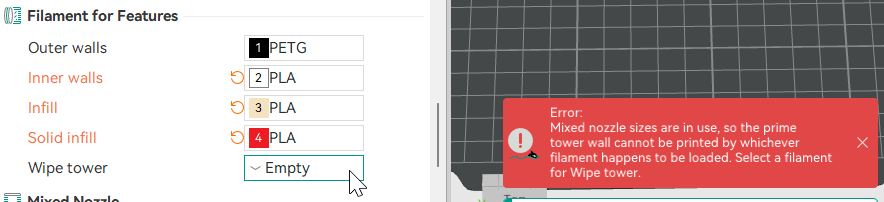
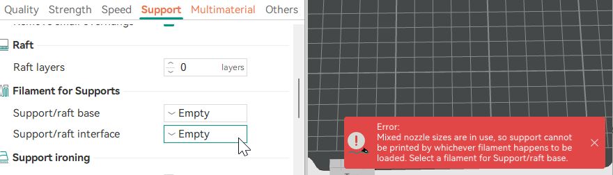
Why: "Default" means whichever filament is already loaded prints this. Under mixed nozzles that is not a safe choice. Support paths are generated once, at slicing time, with a single flow; the tool is not chosen until G-code export, where it can be reassigned onto already-generated extrusions that nothing re-renders. A path built for a 0.2 mm nozzle could be handed to a 0.8 mm nozzle. Silently landing on Nozzle 1 is exactly the bug this guard prevents, so the field is deliberately not auto-filled.
On a uniform-nozzle machine "Default" behaves exactly as before, and none of this appears. Projects saved before 8.4 may open with these fields blank; the slicer will tell you which one it needs.
Nozzle Arrangement Must Be Verified Before Printing
What you see: After slicing a mixed-nozzle plate, the Print and Export G-code file buttons stay disabled until you click Verify nozzle sizes and confirm that the arrangement shown on screen matches the nozzles physically installed on your printer.
Why: The sliced file bakes in which nozzle prints each feature, by diameter. If the physical arrangement differs from the slice - say the file expects 0.2 / 0.4 / 0.6 / 0.8 but the machine is set 0.4 / 0.4 / 0.4 / 0.2 - the wrong nozzle prints the wrong feature. The guard forces a deliberate check that the slice matches the hardware before it can leave the slicer. If they do not match, the slicer shows an error and names the mismatch; switch to the correct arrangement to clear it.
Known gap: the Verify nozzle sizes button gates the Export G-code file button, but it does not gate the Export G-code... menu option, which can still export without the check. This is a known limitation. In practice it is harmless: the Snapmaker U1 firmware does not allow mixing nozzle sizes, so a mixed-nozzle G-code file exported that way cannot be printed on the machine anyway. See First Launch for the full slice-and-print flow.
Line Widths Are Absolute Millimeters, Not Percentages
What you see: The U1 process presets specify line widths in mm (0.42), not as a percentage of nozzle diameter (105%).
Why: A percentage line width resolves against one nozzle diameter. In a mixed-nozzle print there is no single nozzle diameter for it to resolve against - the perimeter generator runs in the outer wall nozzle's context, so a percentage would silently apply the OW nozzle's diameter to extrusions being made by a completely different nozzle.
If you build a custom process preset, keep line widths in mm. A percentage will not error; it will just quietly produce wrong flow on every nozzle but one.
Layer Height Is Bounded by the Smallest Nozzle in Use
What you see: All four nozzles print at one shared layer height, and you cannot raise it above what the smallest nozzle in use can handle. Layer height and initial layer height are a single global setting, shown below the per-nozzle tabs. If your input value is outside the layer height range of the smallest nozzle diameter in use, you get an auto-adjust prompt. That range is set in the PTP, and is usually 0.3x to 0.7x of the nozzle diameter.
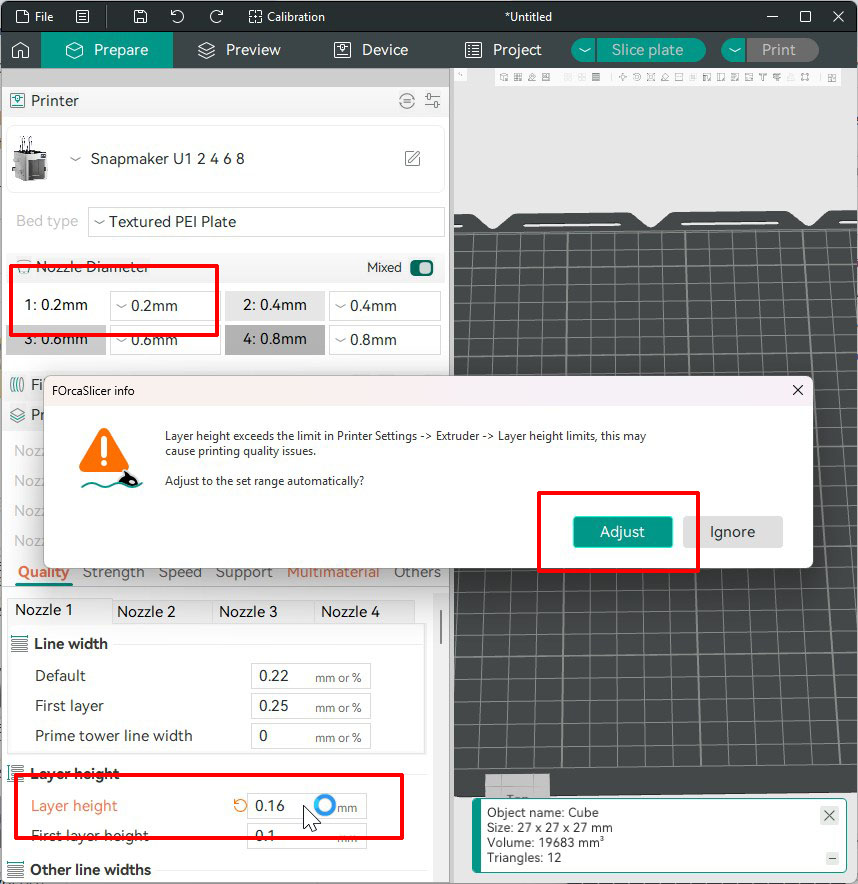
If you choose Adjust, the value is set to the lowest or highest bound of the range.
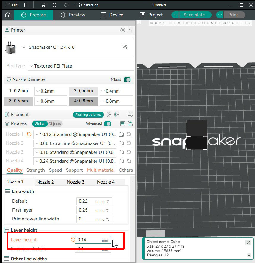
If your input is larger than the smallest nozzle diameter in use, you get an error that refuses to print.
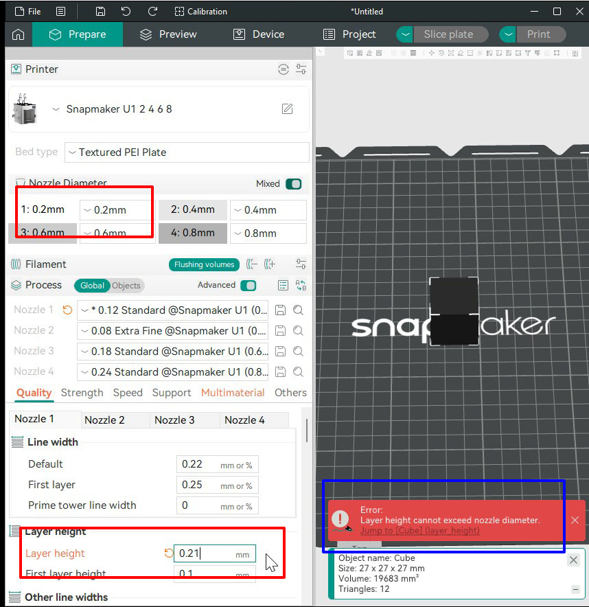
Why: Today, the object is sliced on a single layer grid. Every nozzle prints on that grid. The grid's spacing must be printable by every nozzle using it - which means the smallest one in use sets the ceiling. The limit follows your assignments: drop the 0.2 mm nozzle from the print and the allowed range opens up. Note that the object's own filament counts as "used" - an object left on the 0.2 mm nozzle in the object list keeps the ceiling low even if every feature is assigned to larger nozzles.
This is the single largest constraint in FOrcaSlicer, and lifting it is the current focus of development: giving each nozzle its own layer height inside one object, so the 0.8 mm nozzle can lay 0.6 mm layers of infill while the 0.2 mm nozzle lays 0.1 mm layers of outer wall. That work is in progress and is not in this release.