First Launch
The first time you start FOrcaSlicer there are a few one-time prompts to clear and a couple of settings to choose, then a short walkthrough for setting up mixed nozzles. If you have not installed yet, start with Download and Install.
1. Skip the Snapmaker Orca Update Prompt
On first launch you will be told a new version of Snapmaker Orca is available. Choose Skip this version.
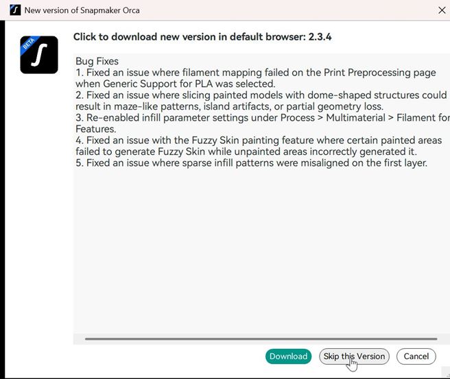
This prompt is inherited from the upstream codebase - it is offering you a Snapmaker Orca update, which is not a FOrcaSlicer release. You are free to update Snapmaker Orca separately whenever you like; FOrcaSlicer should stay a separate install.
2. The Setup Wizard Is Skipped
FOrcaSlicer does not run the Snapmaker startup wizard. The wizard requires a Snapmaker account login, and the presets it downloads are from a newer Snapmaker release that this codebase cannot read.
FOrcaSlicer ships with the Snapmaker U1 presets from the 2.3.1 release, built in. There is nothing the wizard could fetch that you need.
Automatic system preset sync is also disabled by default, for the same reason. Leave it off. See Technical Guardrails for the full explanation.
3. Choose Your Region
Open Preferences.
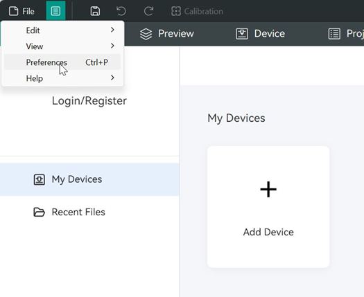
Select your language and region.
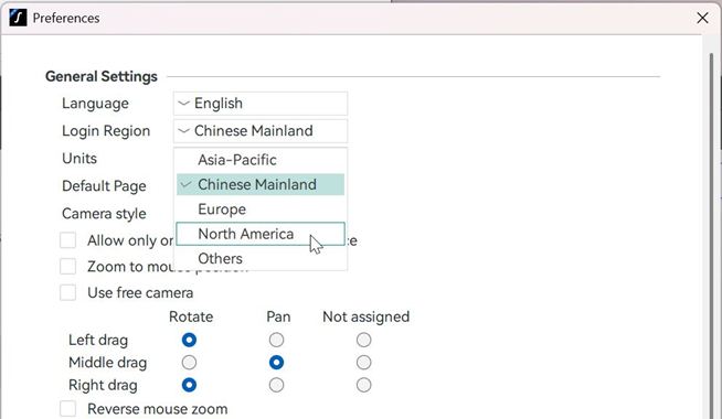
While you are in here: you can also choose which mouse button drags to rotate, which pans, and which is unassigned. This is a FOrcaSlicer addition, not in Snapmaker Orca.
4. Add the Printer if It Is Not Listed
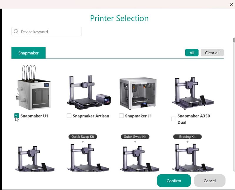
If Snapmaker U1 does not appear in the printer dropdown, click here:
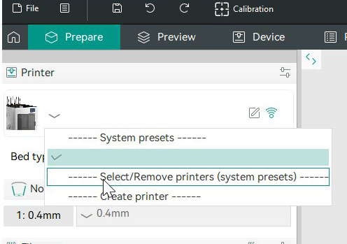
and select Snapmaker U1.
5. Setting Up Mixed Nozzles
Please follow the steps below carefully:
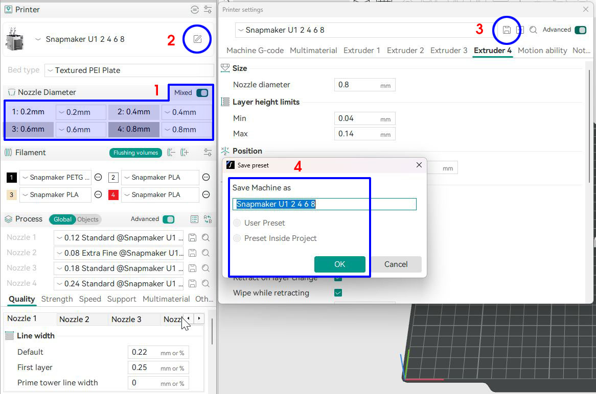
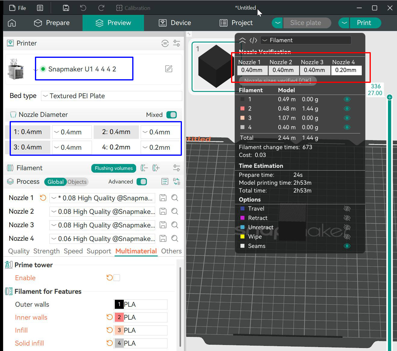
- In the sidebar Nozzle panel, switch Mixed mode on and confirm you want to continue with Mixed mode. Set each of Nozzle 1 - Nozzle 4 to its physical diameter (0.2 / 0.4 / 0.6 / 0.8 mm in this example).
- Open Printer setting window.
- Click Save current Machine next to printer preset (PTP) dropdown.
- Input a PTP name reflecting your nozzle arrangement (recommended), and click OK.
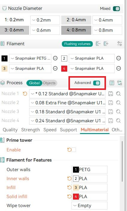
- Assign roles in Print Settings -> Multimaterial -> Filament for Features: Outer walls, Inner walls, Infill, Solid infill.
- If you use support or a prime tower, pick a filament for Support/raft base, Support/raft interface, and Wipe tower in the same panel. Under mixed nozzles these no longer fall back to Nozzle 1 silently - the slicer shows them as Empty and refuses to slice until you choose, naming the one that is blank. (Projects saved before 8.4 may open with these fields blank for the same reason.)
With Mixed mode on, each nozzle is independent - set four different diameters and assign each feature to whichever nozzle suits it.
With Mixed mode off, changing any nozzle syncs all four to the same diameter and switches to the matching stock preset. This is the standard single-diameter workflow.
FOrcaSlicer also auto-detects mixed mode on load, if the printer preset already has differing diameters.
Naming note: this wiki uses Sparse infill for the interior lattice, matching the slicing terminology. In the FOrcaSlicer UI, that feature is labeled simply Infill.
Per-nozzle process preset, line width and speed
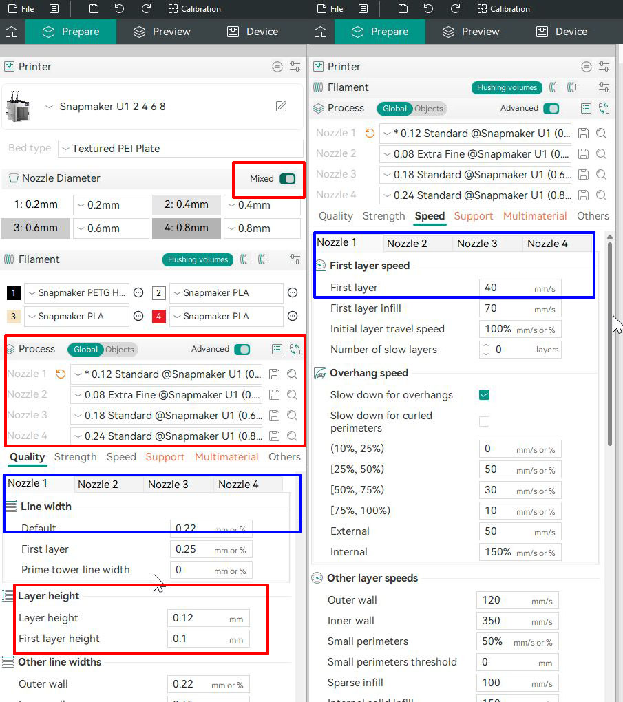
Each nozzle carries its own process preset (PRP) and prints at its own line width and speed. Set them in the per-nozzle tabs (Nozzle 1 - Nozzle 4) on the Quality page (line width, plus a per-nozzle Prime tower line width) and the Speed page. Whichever nozzle a feature is assigned to takes its width and speed from that nozzle's tab. Values typed into the Nozzle 2 - Nozzle 4 tabs take effect immediately; there is no need to reload a preset first.
Per-nozzle speed settings may turn out to be redundant, since Other layer speeds already carries a speed for each feature type. This needs more testing and feedback.
Note: If all four nozzles are the same size, none of this changes anything - output is identical to a single-diameter slice.
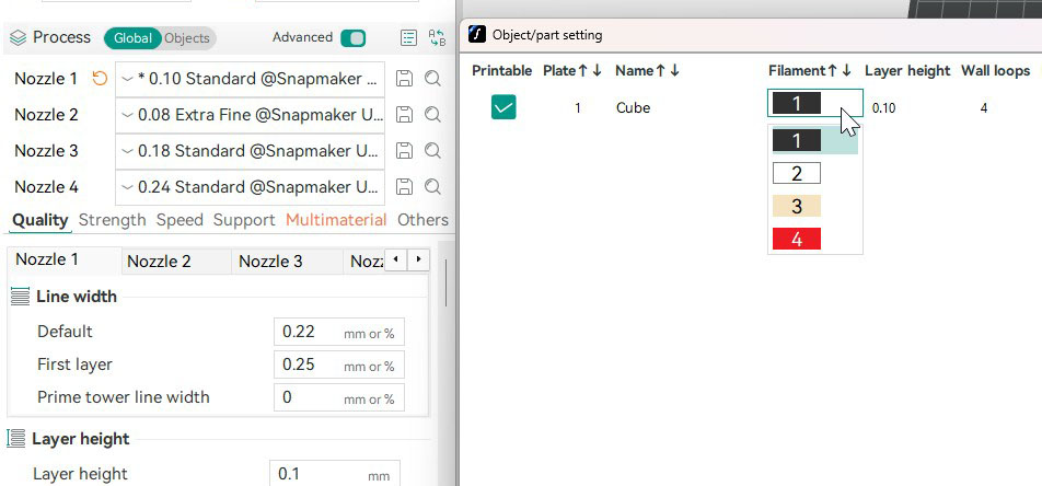
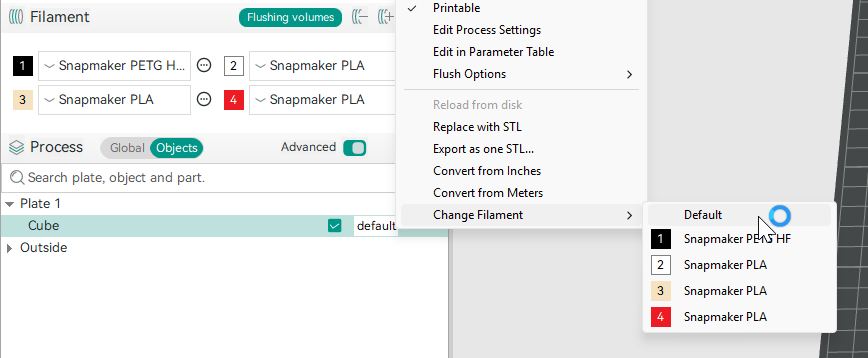
Layer height and initial layer height are the exception - they are a single global setting shown below the nozzle tabs, bounded by the smallest nozzle you actually use. New objects follow the current Print Settings -> Multimaterial -> Filament for Features assignment (Outer walls, Inner walls, Infill, Solid infill). To put a whole object on a single filament instead, there are two ways.
Click View all object's settings (next to the Advanced toggle); in the Object/part setting window, open the Filament dropdown and choose one:
Or open the Objects list, right-click the object, and choose a filament from the Unify Object Filaments menu.
Note on naming: filament and nozzle names are mixed together here. Without FullSpectrum or an AMS, the two terms are interchangeable - they map one to one. With mixed nozzles enabled, that mapping gets muddy. The scope of this FOS release is to focus on using different nozzles to achieve detail levels or functional and aesthetic goals; further integration with FullSpectrum and/or an AMS is beyond the current scope and needs more developer collaboration.
A note on process presets
FOrcaSlicer now lets each nozzle pick its own process preset (PRP). The line width and speed a nozzle prints at follow from its diameter together with the filament and process presets you choose for it. The built-in Snapmaker Orca v2.3.1 presets offer only limited filament choices for nozzles other than 0.4 mm - but you are free to type in whatever values suit the print, or build your own presets. Keep in mind that layer height and first layer height are clamped by the smallest nozzle in use; if a layer height value triggers an error, use the steps above to move the object off the smallest nozzle.
6. Slice and Print
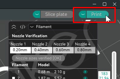
When you are ready, click Slice plate or Slice all. Before the print is released, you are prompted with a Verify nozzle sizes button - a technical guardrail. Make sure the listed nozzle sizes match exactly how the nozzles are arranged on your printer (see Before You Print for nozzle replacement). Only click Verify nozzle sizes if the listed arrangement matches your printer exactly.
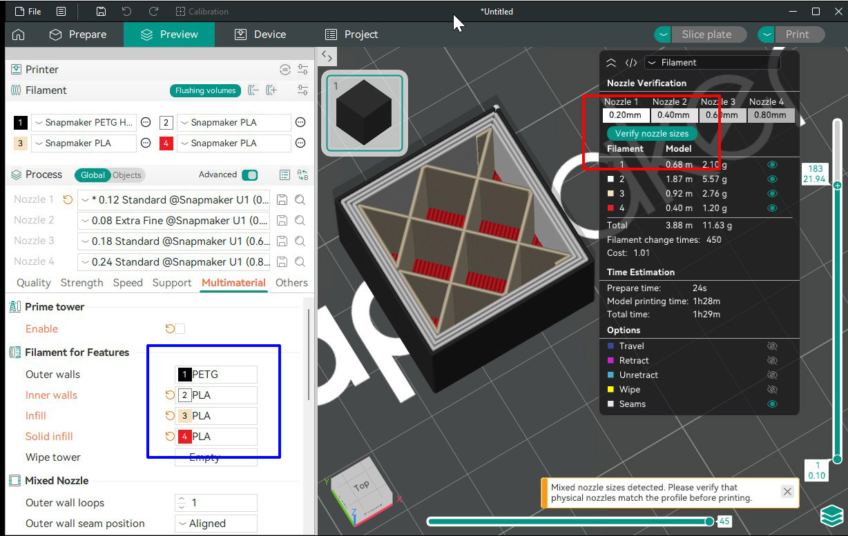
Known limitation: the Verify nozzle sizes button also gates the Export G-code file button, but it does not gate the Export G-code... menu option. That menu path can bypass the guard - but the Snapmaker U1 firmware does not allow mixing nozzle sizes, so you cannot print such a file on the printer anyway.
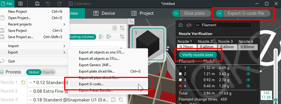
Once verified, the Print button is released. Clicking Print takes you to the next screen.
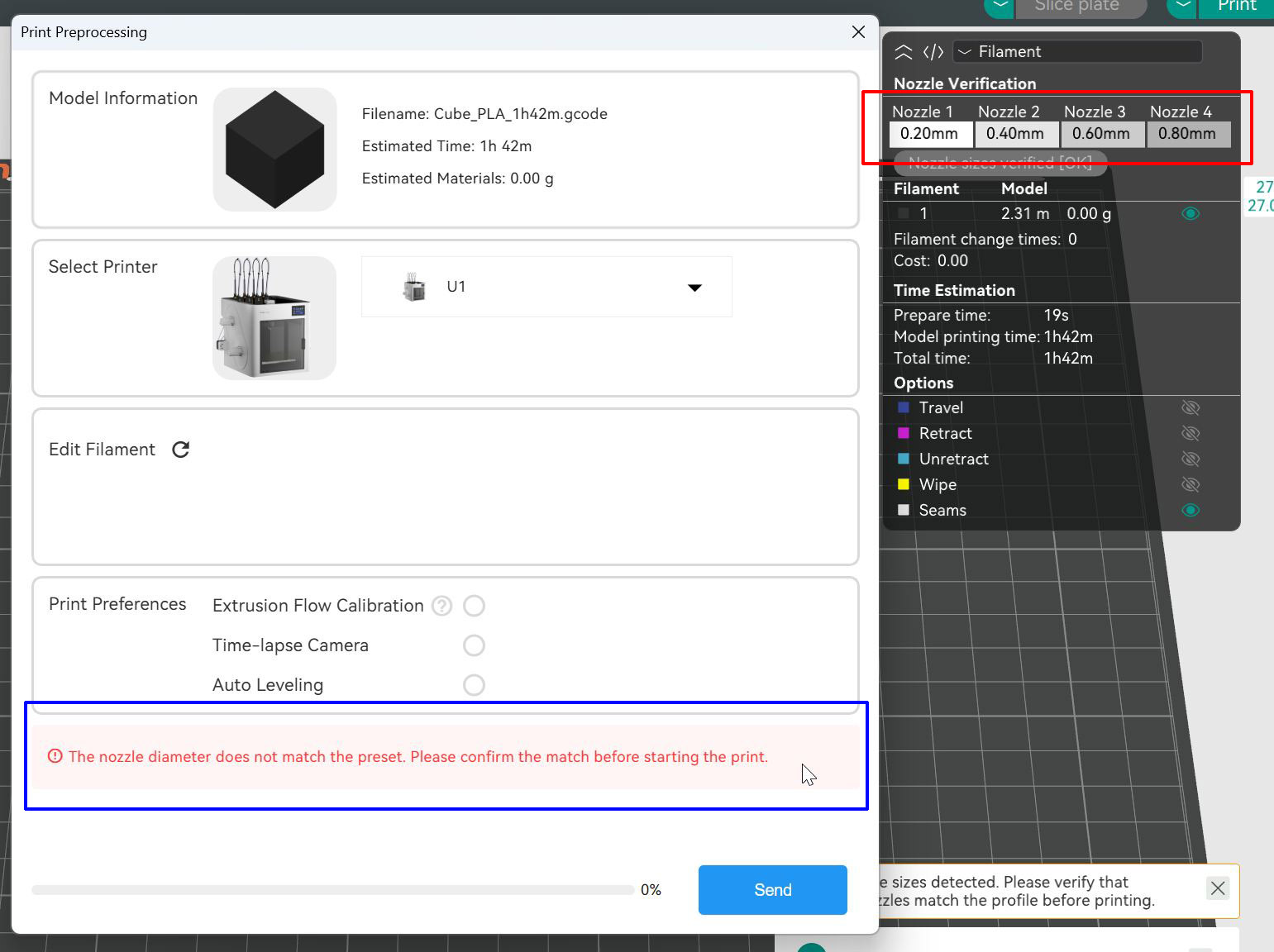
If your sliced nozzle arrangement does not match the printer's configuration - for example 0.4 / 0.4 / 0.4 / 0.2 - you get an error.
After switching to the correct arrangement, the nozzles match and you can continue.
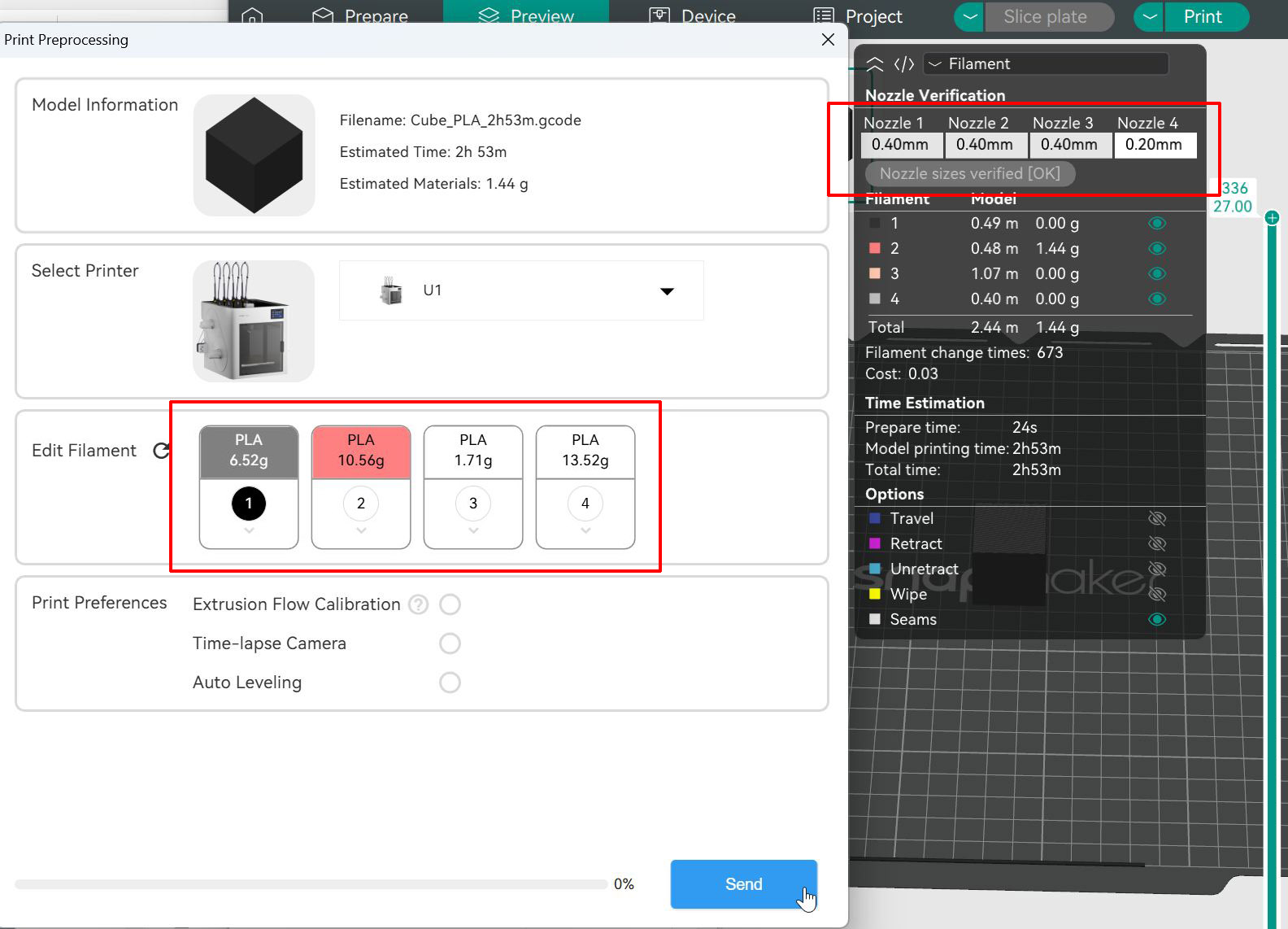
On the next screen you can verify filament assignment. This is the last software safeguard - make sure every selection is correct before sending to print.
Before you print, make sure the hardware matches: see Before You Print for nozzle selection, hot end replacement, and firmware configuration.
Drag-and-Drop May Not Work Until First Run
On a clean machine that has never had OrcaSlicer installed, dragging an STL onto the FOrcaSlicer window may do nothing. Opening the file from File -> Import works normally. Running stock OrcaSlicer once registers the shell handler and might fix drag-and-drop. This is a known installer issue - see Known Limitations.